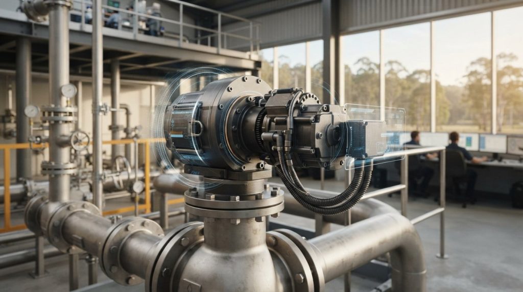
Specifying electric valve actuators based solely on nominal flange torque ratings is often the quickest route to unpredicted plant trips. True operational reliability demands synchronising dynamic motor torque curves and digital telemetry directly with severe-service breakaway demands, rather than simply matching an ISO 5211 bolt circle.
If you’ve ever dealt with unscheduled plant shutdowns caused by thermal motor overloads, duty cycle miscalculations, or troublesome fieldbus integration, you know how unforgiving automated flow control can be. You need actuation packages that seat reliably on every stroke without inflating capital expenditure or compromising hazardous area compliance.
This guide provides a rigorous engineering framework for specifying, sizing, and integrating electric valve actuators across demanding industrial processing applications. You’ll explore essential mechanical torque profiling, international duty classifications, and modern digital communication protocols to eliminate parasitic instrument air demands while maintaining uncompromising plant integrity.
Key Takeaways
- Master the electromechanical drive architecture to understand how motor selection, gearing reduction, and feedback switches govern continuous positioning stability.
- Evaluate lifecycle efficiency trade-offs between pneumatic drives and electric valve actuators, identifying strategies to eliminate parasitic compressor power losses.
- Calculate comprehensive valve torque demand profiles across unseating, dynamic run, and reseating phases to apply proper safety factors for severe service media.
- Compare modern supercapacitor energy storage against mechanical spring-return cartridges to guarantee reliable emergency fail-safe shutoff in hazardous plant areas.
- Implement standardised ISO 5211 mechanical mounting and commissioning procedures that eliminate stem side-loading, bracket deflection, and environmental moisture ingress.
Fundamentals of Electric Valve Actuators in Industrial Flow Control
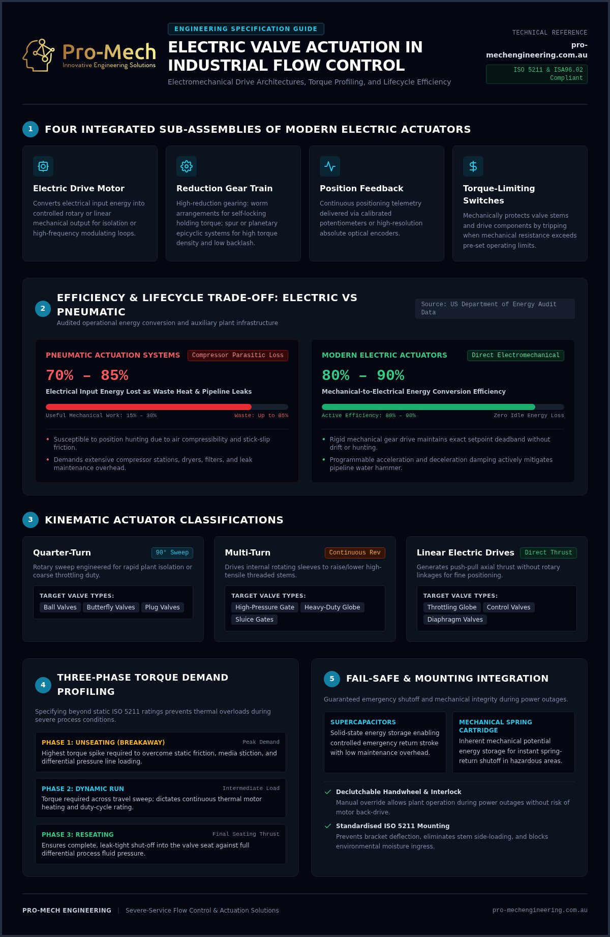
An electric valve actuator functions as the electromechanical nexus between plant supervisory control architectures and physical fluid dynamics. At its core, the device is a specialised electromechanical drive mechanism that converts electrical input energy into controlled rotary or linear mechanical force. Operating under either full-stroke isolation or modulating process control, modern electric valve actuators integrate four primary sub-assemblies: an electric drive motor, a high-reduction gear train, a position feedback potentiometer or absolute optical encoder, and calibrated torque-limiting switches. Understanding these fundamental valve actuator operating principles ensures engineers can match the unit’s mechanical response directly to pipeline dynamics without inducing premature mechanical wear.
Mechanical Drive Architectures and Motion Conversion
Internal transmission design dictates mechanical efficiency, torque transmission, and backlash tolerance. Worm gear reductions provide exceptional holding torque and inherent self-locking characteristics, preventing fluid back-pressure from driving the valve off-seat. However, their sliding tooth contact yields lower mechanical efficiency than spur or epicyclic planetary gear trains. Planetary arrangements offer high torque density and minimal gear backlash within a compact footprint, making them ideal for high-cycle modulating loops. For multi-turn and linear outputs, rotary torque translates into axial thrust via a high-tensile threaded drive stem and drive nut. During commissioning or facility power outages, an integrated declutchable manual handwheel with a mechanical interlock permits manual operation without back-driving the motor.
Quarter-Turn, Multi-Turn, and Linear Operational Classifications
Actuator classification aligns directly with final control element kinematics across processing infrastructure:
- Quarter-Turn Actuators: Deliver a precise 90-degree angular sweep, driving ball, butterfly, and plug valves for both rapid plant isolation and coarse throttling.
- Multi-Turn Actuators: Provide continuous revolution output to rotate internal drive sleeves, raising or lowering threaded stems on high-pressure gate valves and heavy-duty globe configurations.
- Linear Electric Drives: Generate direct push-pull axial thrust, eliminating external rotary-to-linear linkages to deliver high-resolution positioning on throttling globe control valves.
Each profile supports either open/close isolation or high-frequency modulating duty, dictating motor selection and thermal duty cycle parameters across the plant.
Electric vs Pneumatic Actuation: An Engineering Trade-off Analysis
While pneumatic drives deliver raw stroke velocity, electric actuators provide superior positional repeatability and zero parasitic idle energy draw. Evaluating flow control options requires moving beyond upfront purchase figures to calculate the true lifecycle cost of instrument air generation. According to industrial audit data from the US Department of Energy, typical compressed air systems lose between 70% and 85% of electrical input energy as waste heat and distribution pipe leaks. Conversely, modern electric valve actuators operate at 80% to 90% mechanical-to-electrical efficiency, drawing power almost exclusively when repositioning the valve stem.
Operational Dynamics and Positional Precision
Pneumatic cylinders frequently struggle with dynamic position hunting caused by the compressibility of air and mechanical stick-slip friction. In contrast, rigid mechanical gear drives hold an exact setpoint regardless of fluctuating pipeline pressures. By referencing established ISA96.02 electric actuator specifications, process engineers can configure tight deadband resolutions over 4-20 mA loops or digital buses without inducing hunting. Controlled motor ramp-up and deceleration profiles also provide programmable mechanical damping, actively mitigating water hammer shock waves during rapid pipeline shut-off events.
Infrastructure Footprint and Total Cost of Ownership
Eliminating pneumatic lines removes extensive auxiliary plant overhead across processing facilities. Consider the direct infrastructure comparisons:
- Ancillary Maintenance: Pneumatic systems mandate continuous operational monitoring of desiccant air dryers, oil-mist coalescing filters, and pressure regulators to avoid frozen lines and choked pilot ports.
- Installation Simplicity: Rigid stainless tubing and bulk instrument headers give way to streamlined electrical conduits and fieldbus network cables, reducing site labour during plant fit-outs.
- Emissions Compliance: Phasing out natural gas-driven pneumatic devices eliminates fugitive methane venting. This shift directly supports global abatement targets, including the US EPA 40 CFR Part 60 Subpart OOOOb mandates requiring zero-emissions process controllers.
For operations assessing site-wide electrification, partnering with specialist teams to design complete actuated valve packages ensures seamless integration between power distribution grids and process piping systems.
Critical Engineering Criteria for Sizing and Specifying Electric Actuators
Never size an electric actuator to match bare valve torque; dynamic line pressure and scale accumulation demand calculated torque headroom. Commodity sizing tables that assume clean, ambient liquid service routinely fail in heavy processing environments. Rigorous mechanical specification balances dynamic fluid forces, worst-case differential pressures, and thermal motor limits before selecting final drive components.
Torque Profile Characterisation Across the Stroke
Valve torque is dynamic rather than constant. A quarter-turn ball or butterfly valve requires peak torque during breakaway to pull the closure member from the elastomer or metal seat. Once unseated, running torque drops significantly before rising again at end-of-stroke seating. High differential pressures create intense dynamic fluid forces across disc profiles, increasing stem friction. Standard sizing multipliers must be applied over catalogue breakaway torque:
- Clean liquids and lubricating media: 1.20 to 1.25 (20% to 25% safety margin)
- Dry gases, wet steam, and clean air: 1.30 to 1.35 (30% to 35% safety margin)
- Abrasive slurries, mine tailings, and viscous process fluids: 1.50 to 2.00 (50% to 100% safety margin)
Calculations must verify that peak drive output remains strictly within the valve’s Maximum Allowable Stem Torque (MAST) to prevent twisting the drive stem during an unseating event.
Motor Duty Cycles and Thermal Management
Duty cycle ratings determine how often a motor can cycle without overheating. Under EN 15714-2 and IEC 60034-1, motors are classified into distinct service ratings:
- S2 Short-Time Duty (Class A/B): Rated for 15-minute or 30-minute intermittent operation, engineered for basic on/off line isolation.
- S4 Intermittent Periodic Duty (Class C/D): Features a cyclic duration factor (typically 25% to 50% ED) and handles 600 to 1,200 starts per hour for continuous PID throttling loops.
Specifying an S2-rated unit on a modulating control loop results in rapid thermal trips and premature stator burnout. Historical data from motor-operated valve actuator testing highlights how degraded voltage conditions exacerbate this thermal winding stress, accelerating insulation breakdown under sustained load.
Environmental Ingress and Enclosure Protection
Plant environments subject field equipment to severe climatic stress. Specifying electric valve actuators requires matching ingress ratings to operating conditions, opting for IP67 enclosures for standard plant washdown and IP68 for submersible pits. Internal thermostatic space heaters are mandatory to prevent diurnal temperature cycling from drawing moist air through conduit lines, causing internal condensation on circuit cards. For cryogenic lines or high-temperature steam lines exceeding 150°C, physical bonnet extension brackets isolate the actuator electronics and gear lubricants from destructive thermal conduction.
Control Architecture, Fail-Safe Technologies, and Hazardous Area Compliance
Integrating modern electric valve actuators into supervisory platforms requires aligning physical fail-safe mechanics, digital signalling networks, and explosive atmosphere safety standards. Today’s control architectures bridge simple discrete field wiring with intelligent telemetry, giving plant operators predictive insight into valve health while maintaining strict functional safety baselines.
Emergency Shutdown and Fail-Safe Energy Storage
Fail-safe functionality in electric actuation historically relied on bulky mechanical spring-return housings or maintenance-intensive battery backup packs. Modern intelligent actuators increasingly incorporate solid-state supercapacitor power modules. These electrostatic units deliver millions of charge-discharge cycles across extreme temperature profiles without chemical degradation. Upon primary power loss, the stored energy drives the motor to a pre-programmed emergency shutdown (ESD) state: fail-open, fail-close, or fail-in-place. Incorporating automated Partial Stroke Testing (PST) allows SIL 2 and SIL 3 functional safety loops under IEC 61508 to verify valve seat release without interrupting plant throughput.
Industrial Communication Protocols and Real-Time Telemetry
Plant command topologies have advanced well beyond point-to-point 4-20 mA analogue loops and hardwired 24 VDC dry contacts. Digital bus architectures, including Modbus RTU, Profibus DP, and industrial Ethernet networks, allow single-cable infrastructure to transmit operating commands alongside deep device analytics. With Ethernet-APL providing 10 Mbit/s bandwidth over two-wire field cables directly into classified zones, actuators stream motor current signature analysis, dynamic torque profiles across stroke angles, and cycle tallies directly to supervisory control platforms. This live telemetry flags packing friction and seat wear before an operational stall occurs.
Hazardous Area Certification Standards
Operating in volatile processing environments mandates compliance with AS/NZS 60079 and the international IECEx certification scheme. Field enclosures specified for Zone 1 or Zone 2 explosive gas atmospheres require certified flameproof (Ex db) or increased safety (Ex eb) construction to isolate electrical arcing from surrounding atmospheric hazards. For bulk materials handling, mineral processing, and grain terminals, dust-ignition-proof (Ex tb) enclosures prevent combustible particulate ingress. To engineer certified packages that satisfy these rigorous regulatory requirements, consult with Pro-Mech Engineering Solutions for comprehensive valve automation and integration support.
Procurement, Mounting Integration, and Commissioning Best Practice
Flawless plant automation depends on physical integration integrity. Even the most advanced electric valve actuators fail prematurely if mechanical mounting deflection induces stem side-loading or if site commissioning overlooks torque threshold calibration. Achieving long-term operational success requires adhering to standardised mechanical interfaces and rigorous quality assurance workflows before plant energisation.
Precision Mechanical Mounting and Alignment
Actuator mounting brackets must provide complete structural rigidity under peak stall torque conditions. Specifying mechanical interfaces governed by ISO 5211 standard flange dimensions guarantees precise concentricity between actuator drive bushings and valve stems. Fabricated brackets with inadequate gusseting flex under high breakaway loads, creating lateral thrust that rapidly scores valve stems and degrades gland packing. Utilising CNC-machined mounting brackets and precision zero-backlash drive couplings prevents angular misalignment. Across vibrating piping systems, pairing stainless steel mounting hardware with mechanical thread-locking fasteners prevents vibrational loosening over extended operational cycles.
Electrical Installation and Commissioning Protocols
Environmental ingress remains a leading cause of premature field failure during initial plant construction. Installers must fit certified barrier glands and route cabling through low-point drip loops to prevent moisture running down conduit lines into terminal compartments. Modern intelligent electric valve actuators feature non-intrusive setup tools, allowing technicians to configure optical position sensors, travel end-stops, and torque cut-off levels via infrared or Bluetooth interfaces without opening explosion-proof enclosures. Pre-commissioning requires executing multi-point stroke verifications to validate signal concordance between field position encoders and central control room displays.
Engineered Actuated Packages and Technical Procurement
Treating valves and actuators as disjointed commodity purchases introduces unnecessary commissioning risks. Procuring complete actuated valve packages ensures mechanical mounting hardware, motor torque profiles, and control accessories are engineered and validated together under controlled factory acceptance testing (FAT). Engaging Pro-Mech Engineering Solutions provides access to pre-tested assemblies built for severe industrial applications across Australia. Full-lifecycle support includes in-situ quality inspections, mounting alignment verification, and tailored installation and commissioning plans that ensure process systems transition smoothly from initial dry testing to full automated operation.
Optimising Plant Reliability with Engineered Valve Automation
Modernising process infrastructure requires treating electric valve actuators as engineered electro-mechanical systems rather than interchangeable components. Factoring dynamic torque safety margins, matching motor duty classifications to process control loops, and enforcing ISO 5211 mounting rigidity protect production lines from unscheduled thermal overloads and stem binding.
Achieving dependable performance in demanding Australian mining, chemical, and power generation facilities starts with sound procurement. Pro-Mech Engineering Solutions integrates premium DelVal and ValvTechnologies assemblies into bespoke actuated packages validated through rigorous factory testing. Supported by in-situ quality inspections and structured commissioning plans, our engineering specialists ensure every automated unit meets exact site specifications. Partner with Pro-Mech Engineering Solutions for high-specification actuated valve packages and technical commissioning to safeguard your facility’s operational integrity.
Frequently Asked Questions
What is the primary difference between quarter-turn and multi-turn electric valve actuators?
Quarter-turn electric valve actuators rotate through a strict 90-degree arc, making them the standard choice for ball, butterfly, and plug valves. Multi-turn units rotate through multiple full revolutions to drive an internal threaded drive sleeve, which raises or lowers the non-rotating stem of rising-stem gate or globe valves. The choice depends on the valve’s mechanical design and whether flow isolation requires angular disc positioning or linear wedge travel.
Can an electric valve actuator achieve a reliable fail-safe position during a total plant power outage?
Yes, modern electric valve actuators achieve emergency shutdown using integrated mechanical springs or solid-state supercapacitors. While mechanical spring-return designs deliver instant unpowered snap-acting closure, internal supercapacitor modules store sufficient electrostatic energy to drive the motor to a pre-set safe position, whether fail-open, fail-close, or fail-in-place. Unlike legacy battery backups, supercapacitors require zero chemical maintenance and operate reliably across extreme plant temperature swings.
How do I calculate the required torque rating when pairing an electric actuator with an industrial valve?
Start by identifying the valve’s peak breakaway torque under maximum operating differential pressure. Next, apply an engineering safety factor matched to the process fluid, typically 20% for clean lubricating fluids and 50% or higher for slurries or dry gases. Verify that the actuator’s rated output satisfies this adjusted figure while remaining below the valve’s maximum allowable stem torque (MAST) to prevent drive stem distortion during unseating.
What international and Australian standards govern electric actuators in hazardous or explosive plant areas?
In Australia, explosive atmosphere equipment must comply with AS/NZS 60079 and the international IECEx framework. These standards mandate flameproof (Ex db) protection for Zone 1 or Zone 2 gas areas, and dust-ignition-proof (Ex tb) construction for combustible dust hazards found in mining and materials handling. Field units must maintain appropriate temperature classifications, typically T4 or T6, alongside minimum IP66 or IP67 ingress protection against severe environmental conditions.
Is it more cost-effective to automate valves with electric actuators or pneumatic cylinders in processing plants?
Pneumatic cylinders offer lower initial equipment costs, but electric actuators often yield lower total lifecycle expenditure by eliminating dedicated instrument air infrastructure. Compressors waste up to 85% of electrical energy as heat and line leakage, requiring continuous maintenance on dryers, filters, and regulators. In contrast, electric drives draw power almost solely during stem movement, providing superior positioning resolution without ongoing compressor overhead or fugitive gas emissions.
What maintenance routines are required to ensure the long-term reliability of industrial electric actuators?
Preventative maintenance centres on verifying gearbox lubricant condition, checking terminal compartment seal integrity, and inspecting anti-condensation space heater operation. Periodic non-intrusive diagnostic log downloads let engineers track motor current draw and dynamic torque profiles over time. Comparing these historical curves against baseline commissioning data reveals increasing stem friction, packing binding, or mechanical seat wear well before unexpected equipment stalls interrupt plant production.